THE FACTS
Super glue was originally intended for medical purposes, but has not been FDA approved for human use for "potentially" being toxic. Studies from around the globe have shown that the potential for toxic poisoning would really require abundant use. Some side effects will or can include skin, eye irritation. THERE ARE OVER THE COUNTER BANDAGE GLUES THAT ARE FDA APPROVED. They have a slightly different chemical structure that makes it basically better for consumer use.
1.Seeping wounds must be able to drain
2.Super glue makes eyes sting and or burn
3.Super glue react to cotton and baking soda by getting extremely hot...DO NOT USE Q-tips or cotton balls
THE METHOD
1. Examine the wound.
Is it filthy, contaminated or at great risk of infection? The act of bleeding is a form of cleaning the wound and is a wonderful natural method when there is a lack of foreign debris in the effected area. Allow the wound to bleed a little. However if internally there is bleeding that does not stop on its own ( with basic pressure and a cool lint free towel) within a few minutes there may be a cut vein, or artery and super glue IS NOT THE ANSWER.
2. There are two wounds that can be dealt with using Super Glue. Each require their own method.
A purely cosmetic injury that does not rip, tear or destroy the muscle tissue or artery can be sealed. Apply a sparing amount of glue along the "closed" wound. I put a large amount of glue on a plastic toothpick allowing the glue to run down the plastic until it contacted the wound. Comfort your dog and keep them as calm and still as possible for the next few days to come. Do not allow scratching that might tear open the wound, and inspect for quality of hold every few hours, as more may need to be applied around the three or four day mark.
Hold the wound together for several minutes as the glue dries. Make sure to apply small amounts of Hydrogen peroxide on the wound every evening, and do not allow the animal to go play in the yard, toilet, or garbage.)
( I did this to prevent any reaction from the dog causing any actual glue entering the wound.I could only imagine her being dis-comforted and driving the entire bottle into her wound on accident. )
A wound that is likely to build up fluid must not be completely sealed and requires that small areas of the cut are allowed to seep. In a surgical environment a drain would be sewn in ( I have had this done to one of my own injuries) So do not cover the entire wound with a huge amount of glue.
THE STORY
The gash in her head was about 3 inches long and exposed the insides of her head to the world. With her freshly cut hide resting its its most natural position, you could see the flesh that wrapped the back of her eye socket, the muscles on the top of her head, and the fatty tissue between her hide and skull. Shaken up and pumped full of adrenaline, she was not fighting our attention at all. ( A VERY IMPORTANT POINT ) PLEASE READ ALL OF THIS ARTICLE BEFORE ATTEMPTING ANY MEDICAL ATTENTION TO YOUR ANIMALS!
Roughly two weeks ago my two year old bitch had just came out of heat. What started out as a flirtatious display of dominance turned suddenly viscous as the female had went from allowing herself to be dominated to restoring her order in the household. It only took a second and both dogs were latched on. I did not waste any time separating the animals, but like high school children they took turns beating each other. Every time I gained control of one dog the other grabbed on as I held one helplessly. I essentially ended up holding one as the the other bit, and then holding the other as they returned the favor. ( lesson learned )
While in heat she spent a lot of time with her normal best friend dog she has known for years. During the mating cycle for dogs their demeanor is quite different than it is from day to day. As part of the dogs mating ritual, they tend to rough house as a form of flirtation. Its not uncommon for the "Dominant" female to allow herself to be "dominated for the purpose of mating. When the mating season comes to an end she can change back to demanding her dominant role back. This very act can confuse the Male dog and he may try to defend his newly found "Dominant" role.
In this case the male dog had grown to the point her entire head fit in his mouth. His place as "dominant" dog has now been marked.
Just to start this off. I am not a Veterinarian. I am not a doctor and this procedure is an account of actual happenings. This is in NO WAY SHAPE OR FORM advice or direction intended to replace the proper care for mammals of ANY sort.
I ran out and physically broke up this dog fight by placing myself in the middle of it, and I did get bit. Luckily it was my dog that bit me, and the simple vocal reprimand of my voice was sufficient to get her to stop. I suggest trying to spray the dogs with a garden hose first if the method is available. In my case it was not an option, as the winter season requires we disconnect them to prevent freezing.
Before attempting to provide any form of medical care to your dog, use caution. A hurt animal can often turn on its owner from fear alone. I remember my father having to shoot our dog that got hit by a car. We were very young, and did not witness it first hand. The poor dog would not let anyone near her to pick her up.
Saturday, March 24, 2012
Wednesday, June 29, 2011
unclogging a bathtub with a wash cloth and a milk jug!
Unclogging a bathtub with a washcloth and a milk jug?
If you have already tried a chemical compound such as liquid plumber, un-successfully, do not proceed. The remaining chemicals produce a risk of serious injury and chemical burn to the hands, face, and eyes.
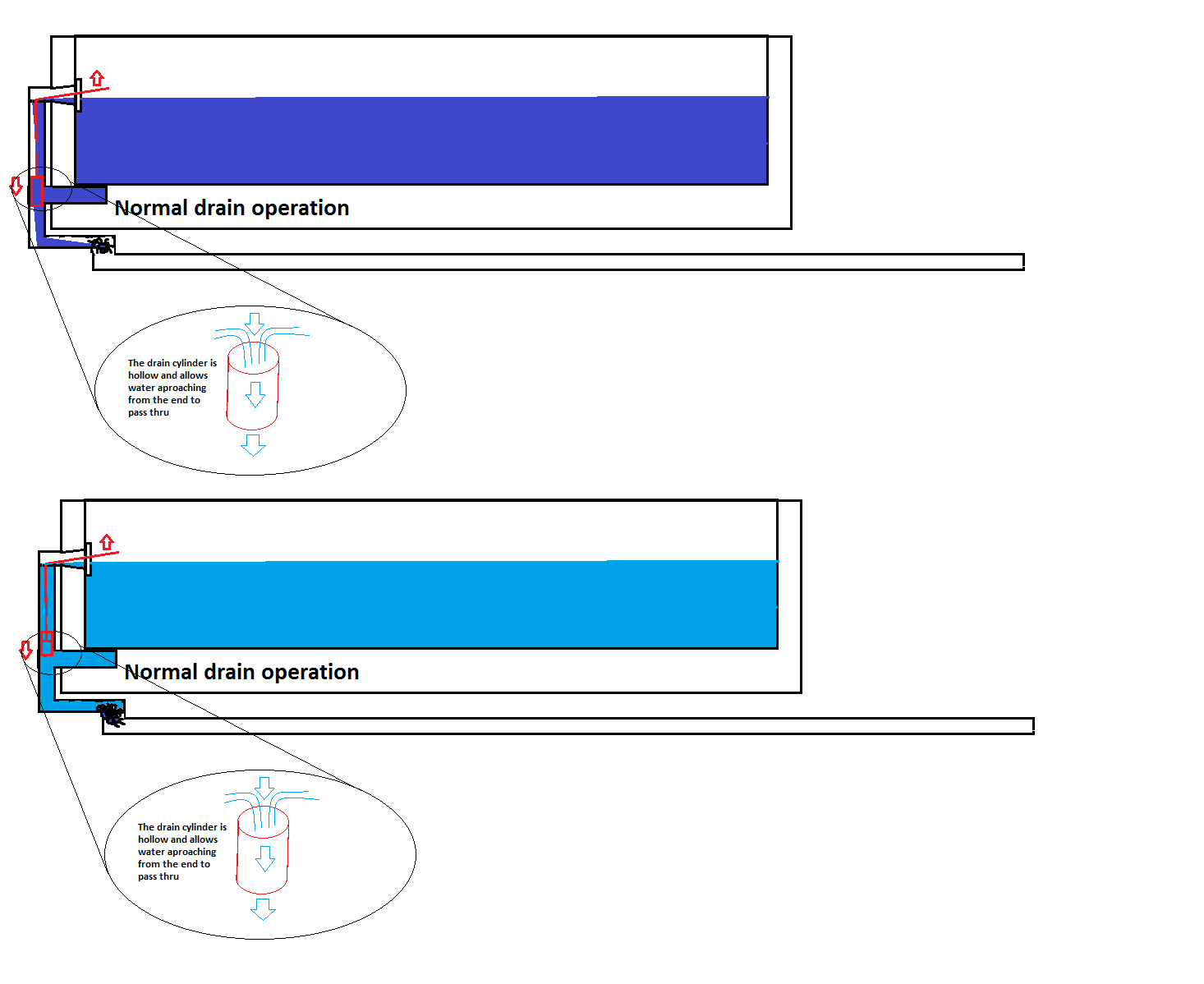
Yeah. It can be done. The bathtub will often throw people for a loop because when you use the plunger, you can hear all of the water rushing through the over flow. That is where most of the trouble lies with unclogging a bathtub. The typical use of a plunger uses hydraulics to force the movement of a blockage. Unfortunately, the water will follow the path of least resistance. That will end up being the drain vent.

1. The first thing you will have to do is take the two screws out of the vent / overflow on the bathtub. You will then need to pull up and outward on the cover. Some of the bathtub drains have the plugging mechanism in the overflow. These overflows are fitted with a little flip lever in them. You will have to remove the drain mechanism completely.

2. Once you have removed that part of the bathtub drain assembly you will need to saturate a thick wash cloth and stuff it snugly into the drain overflow. Use caution to be sure the wash cloth fits tight and still make sure it can be reached and removed. You can control this by how you feed it down the pipe. You want the washcloth to seal the pipe from escaping air or water. The purpose is to create a sealed system. A sealed system allows the pressure to build up and follow the path of least resistance. The quality of your “washcloth seal” will need to be more secure than the hair clog in the drainpipe.

3. You will now need to fill the bathtub half way with water. Hot water is more likely to help with cutting soap scum that might be holding your hair clog in place. Please make sure the water is not hot enough to cause yourself injury when placing your hands in the water.
4. Fill a milk jug or water jug with hot water as well.

5. Invert the jug quickly and place it in the tubs bottom drain. In the same motion, apply violent force to the milk jugs bottom face. This will crush the milk jug, thus forcing all of the water into the drain. This might need to be repeated as many as twenty times, but it can be successful the first time as well. Keep an eye on your washcloth seal, listen for escaping air or water from around the washcloth. I will try to make illustrations that show how and why it works. I hope that with all of that, you are able to see what is making this work, and the importance of tight seals.
If you have already tried a chemical compound such as liquid plumber, un-successfully, do not proceed. The remaining chemicals produce a risk of serious injury and chemical burn to the hands, face, and eyes.
Yeah. It can be done. The bathtub will often throw people for a loop because when you use the plunger, you can hear all of the water rushing through the over flow. That is where most of the trouble lies with unclogging a bathtub. The typical use of a plunger uses hydraulics to force the movement of a blockage. Unfortunately, the water will follow the path of least resistance. That will end up being the drain vent.

1. The first thing you will have to do is take the two screws out of the vent / overflow on the bathtub. You will then need to pull up and outward on the cover. Some of the bathtub drains have the plugging mechanism in the overflow. These overflows are fitted with a little flip lever in them. You will have to remove the drain mechanism completely.

2. Once you have removed that part of the bathtub drain assembly you will need to saturate a thick wash cloth and stuff it snugly into the drain overflow. Use caution to be sure the wash cloth fits tight and still make sure it can be reached and removed. You can control this by how you feed it down the pipe. You want the washcloth to seal the pipe from escaping air or water. The purpose is to create a sealed system. A sealed system allows the pressure to build up and follow the path of least resistance. The quality of your “washcloth seal” will need to be more secure than the hair clog in the drainpipe.
3. You will now need to fill the bathtub half way with water. Hot water is more likely to help with cutting soap scum that might be holding your hair clog in place. Please make sure the water is not hot enough to cause yourself injury when placing your hands in the water.
4. Fill a milk jug or water jug with hot water as well.

5. Invert the jug quickly and place it in the tubs bottom drain. In the same motion, apply violent force to the milk jugs bottom face. This will crush the milk jug, thus forcing all of the water into the drain. This might need to be repeated as many as twenty times, but it can be successful the first time as well. Keep an eye on your washcloth seal, listen for escaping air or water from around the washcloth. I will try to make illustrations that show how and why it works. I hope that with all of that, you are able to see what is making this work, and the importance of tight seals.
Friday, June 24, 2011
Reading a ruler, dividing fractions in half for centering lights etc.
Reading a tape measure and mastering the repeated use of it, in the United States.
Lets’ face the facts; How many people can pick up a tape measure time and time again, and get the same effect every time? I would have to say it took years to get consistent measurements that another person could use my help with. The basics are the fractions, and there is no doubt I did okay with that. All too often we come across people who are un-able to “Do The Math “.
A basic tape measure is broken down into Feet, inches and fractions of individual inches. Lets say you want to center a light fixture on the ceiling of a room; where the rooms dimensions are 155 and 5/8 “ . Starting with the 155 you can instantly notice that half of $1.50 ( or 150 ) is $.75 ( or 75 ) and half of $5 or (5) is $2.50 or (2.5) so half of 155 must be (75+2.5 ) 77.5 or 77 and a ½”. I never divided the 5/8 in half but I swear that is the easiest part.
150 + 5 + 5/8 is the same as 155 and 5/8”
75 2.5 5/16 is half of each simple problem
Any fraction on the tape measure is divided in half simply by doubling the half to quarters, quarters to eighths, eighths to sixteenths, or even the sixteenths to thirty seconds.
For instance half of
1/2 (half, Or two Quarters) is 1/4( One Quarter or 25 cents or .25 ) I use money a lot because our dime is tenths while our quarters are either .25 or ¼ or 2/8 or 4/16 or even 8/32 of a dollar or an INCH..
Why the dime? Simple. Five dimes is a half dollar, AKA $.50, AKA two quarters or even ” 5 out of ten”
(5/10)
So we had 5/8 and half of that must be 5/16 . See how the top number stayed the same. When cutting a fraction in half it will always stay the same on top and double on the bottom. It is a tape measure not a chemical formula for rocket fuel. We do not need to remember our full scholastic history to do this. Just do as I have shown and double the bottom number. Half of 5/8 is 5/16. You can always check math problems by doing the opposite back to it. So just for the sake of testing I want to know what 10/16 is equal to. There is a right way to find out the simplest term, and I can’t remember it. For a tape measure it really is not that relevant how you get to the lowest number, only that one of the two numbers can not be devided by two. So 10 divided by 2 = 5 and 16 divided by 2 = 8 …. 5/8. It worked. Back to the tape measure and the room. 155 divided in half is 75+2.5 or 77.5.
( We can check that the exact same way 70 + 70 is 140 , 7+7 is 14 ,and .5 + .5 is one .)
There for 140+14+1 should be 155 .
40 + 14 is 54 . 54 + 1 is 55. 100 + 55 is 155. So all of that worked out just fine.
Did I loose you? Was it the .5? Remember what $.50 is? A Half dollar right? So although I am adding and subtracting apples from oranges and doubling my mangos; I am still getting down to the proper answer. A half dollar is absolutely equal to 5/10 (because that is exactly what .5 means) .
On the tape measure there are three fractions that equal the exact same as .5. There is the notorious ½” mark; that stands exactly half way between any two individual inch lines. That same mark that also translates into 2 quarters (2/4) 4 eighths ( I have the pot heads attention) and 8 sixteenths (or 8/16) I know this is getting hard to understand but bare with me and I will bring it all together for you right now.
½ = 2/4 = 4/8 = 8/16
The numbers up there are all the same number! Nobody wants to hear; “Cut me one at 8/16ths” but face it I cant put 5/16 with a half either so I have no choice but to convert my half into it’s equal 16th.
I can not add 5/10 to my 5/16 because I don’t think they made a mark for that on my tape measure. I need to find the lowest common denominator….NO! Okay, maybe I do; but I do not care what that means. I just need both numbers to be on the tape measure. I have to go with the 16ths. How many 16ths are there in a half of anything…. Be it a dollar, an inch, or a pizza slice, half of 16 is 8. Now I can finally combine the entire cluster of crap into one stinking answer. 8+5=13 Those were sixteenths I was adding so I have 13/16” and 77 inches. Or 77 and 13/16”.
Now you are asking yourself why the hell I would put myself through three mathematic problems to solve something as simple as a half of anything. Here is why; Every single thing I did above is what I call “ TOP OF MY HEAD MATHEMATICS” Nothing is hard about any of those numbers when they are put in simple terms. I can do all of these ridiculous steps faster than you can forget 155 and 5/8 while you are trying to divide 155 by any number. Or even worse; If you are getting two and a half eighths.
I just walked through the one dimension of the room and I want you to get the easy part. Now we need to center the other dimension of the room which has a measurement of one hundred and ¼” ( 100 ¼”)

DOUBLE THE QUARTER for 1/8th. One eighth is half of one quarter.
So 50 and an 1/8” . Is that what you got? ( I really hope so ).
So now why is it that every time I cut a board it either, does not reach, or I can’t beat it into its place. When I draw A line here under these words would you say it marks the start of this topic, or the end of the last? I cant be guessing which one it is, and the same goes for the marks you make from your tape measure.
This line does not just have one little place. In fact; it has a leading edge, a tailing edge , and a centerline. All three of these locations have different numerical values and until you pick an edge and keep it, you will never cut two boards the same. Trying to cut right down the center of the line always seems to be a pain, because the saw blade is bigger than the line and you can’t tell how much you are cutting off each side of the line. What I make it a point to do is cut the line off on its edge. One edge. I mark my lumber in a way that the edge of my line does not enter my measurement, but edges the measurement. Then I cut the line on tis edge. The side of the blade will ride down the edge of the line and I will keep it there. You have to remember that not only does your line have a depth, but so does the saw blade. Edge of blade to edge of line.
Often when you measure things, they do not line up with the marks on your tape measure. Then it would be referred to as:” light or heavy. “ Light meaning less a line and heavy meaning more a line.

Hanging a chandelier to the right height

Hanging a chandelier.
There is often some leeway with bedroom lights. The expectations people hold are different in the displayed area of the home. I always found it better to attempt perfection in order to make up for imperfection. I want to hang my chandelier over my dining room table and the box is already center. So what we will be looking for here is a height. The light cannot shine directly in the eyes of our diner guest, but still has to be visible from the entryway. The dining room is divided from the rest of the house by a lowered area that looks like beams holding up the ceiling. These beams extend two feet off the ceiling and our table sits three feet off the floor. To achieve a good appeal and a functional lighting arrangement, I want to divide the visible space above the table equally and place the center of the light fixture in that area. Can you tell me how long my chain will need to be?
This is how to accomplish this task.
We will start by getting a ceiling height. Ten -foot ceilings are all the rage. So surely, my ceiling is ten feet high, or 120 inches. I need to subtract 24” for the dropped beams, and 36” for the suspended tabletop. In this case, I can go ….Oh look 2 feet plus 3 feet is 5 feet. Then I can remove those five feet from my equation. I am left with 10 feet minus 5 feet is five feet. Five feet is 60” and that is my ZONE. So far we have the ZONE the fixture should be centered in and in order to do that we need to know what center of the ZONE is. Half of 60 is 30, so we will be calling that the center of the ZONE. We have a center, but no reference point. I cannot very well hold the tape in mid-air and assume that I am centering the zone. We know that the chandelier will hang from the ceiling so we now need to know what the distance of the sweet spot is, to our reference point of the ceiling.
We initially subtracted the 24” from the 120” as a step in deciding center of the zone. 24 inches represents the start of our zone. 30” represents the center of our zone. We now add the 24” to the 30” to represent our centerline from the ceiling. 54” from the ceiling is our target centerline.
Chandeliers have depth, and height. I guess we should assemble the chandelier and measure its height, and figure out what center of that is. I have hung hundreds of chandeliers that averaged in the 18” high range. (Only the fixture, not the chain). Well, half of 18 is nine. This is where it all boils down.
We have a 54” distance to bring the center of the chandelier to. The top half of the chandelier will be above the 54” mark by nine inches. So, when we hang the chain from the ceiling it needs to reach the top of the chandelier, or someone will have to sit there and hold it. 54 – 9 is 45. The top of the chandelier will be 45 inches from the ceiling. Chandeliers also have a box cover known as a canopy and an threaded tube that holds an eyelet intended to attach the chain to. This too is a part of the equation. The assembly is another amount of space that comes out of the chain length. After setting the canopy to match the mounting bracket the total measurement of the assembly will be near 2 and ¾ inches and will subtract from the 45” that was initially the reference point. 45 minus 2 and ¾ is?
Forty four and 4/4 is the same as 45.
So 44 minus 2 is 42 . 4/4 minus ¾ is ¼ . The total chain length will need to be 42 and ¼” !
Tuesday, December 21, 2010
Wiring thermostat for 120v heater
The code requires that all ungrounded conductors are disconnected. The double pole thermostat that you have described is for a 220v heater.
2 wire method

It is crucial for your 120v heater, that there is 120v from black to white! Not 220v
L1 and T1 pass through when there is a demand for heat
L2 and T2 pass through when there is a demand for heat
A house wired prior to 2008 would have the white wire , wire-nutted through even if it was 220v heater system; Where a house wired after 2008 the white wire would have landed on the L2 and again on the T2
If the supply voltage is 120v; Then you only need the L1-T1 side of the thermostat and the L2 and T2 wires are not needed
With the current code the 220v system is required to break all of the line wires.
220v systems that used baseboard heaters did not require a neutral wire; Instead the white wire carries 120v to ground and the black wire also carries 120v to ground. Across each other they measure 210-240v
(A 120v heater should not be used in this situation)
L1 being black (powered wire) and L2 being white (powered side)
The black of the (heater wire) T1 and the white of the (heater wire)
This method will work on the 120v heater as well but is not required. On a 120v heater the thermostat only needs L1(black powered wire) and T1 (Black heater wire)
The white wires can be wire-nutted together and stuffed in the back of the box
3 Wire method
If there is a red, black , white, and ground in the box; This would be a three wire system.
The black wire will be 120v to ground, the red will be 120v to ground, and the white will be a return path. From black to red will be 220v
Use the black powered wire as L1 and the black of the heater wire as T1. Tie the white of the powered wire directly to the white of the heater wire,
In this situation the thermostat only separates and connects the power wires together when there is a demand for heat.
Monday, December 20, 2010
pre 1995 Dodge ECM engine codes
The codes for Pre-1995 Dodge Trucks are retrieved from the ECM, by counting the check engine light flashes.
1.) Turn key on, off, on, off, on......and wait
Then the light will flash for example
On/off/on/OFF......On/off/on/off/on/OFF.............................
This will be a 23 code...
Then it will move on to the next code, until it flashes on a 55 code
on/off/on/off/on/off/on/off/on/off....on/off/on/off/on/off/on/off/on/OFF...........
This will be the 55 code or end of message
So it will read like so
On/off/on/OFF......On/off/on/off/on/OFF............................................
on/off/on/off/on/off/on/off/on/off....on/off/on/off/on/off/on/off/on/OFF...........
.
Below are the OBD DTC's for 1995-previous model year EFI-equipped Dodge vehicles.
11 camshaft signal or ignition signal, no reference signal during cranking
12 memory to controller has been cleared within 50-100 engine starts
13 map sensor not detecting any change during test
14 map voltage too high or too low
15 vehicle speed sensor, no signal detected
16 knock sensor circuit. open or short detected
17 low engine temperature, possible thermostat fault
21 oxygen sensor signal, neither rich or lean detected
22 coolant sensor voltage low
23 air charge voltage high/low detected
24 throttle position sensor voltage high/low
25 automatic idle speed motor driver circuit, short or open detected
26 injectors 1,2,3 peak current not reached
27 injector control circuit does not respond to control signal
31 purge solenoid circuit, open or short detected
32 egr solenoid circuit, open or short detected
33 a/c clutch relay circuit, open or short detected
34 speed control servo solenoid, open or short detected
35 radiator fan control relay circuit, open or short detected
36 waste-gate solenoid, open or short detected
37 part throttle unlock(PTU) circuit, open or short detected
41 charging system circuit not responding to control signal
42 fuel pump or auto shutdown (ASD) relay voltage sensed at controller
43 ignition control circuit not responding
44 battery temperature voltage circuit problem
45 turbo boost limit exceeded-map sensor detects over-boost
46 battery voltage too high
47 battery voltage too low
51 air/fuel at limit
52 logic module fault
53 internal controller failure
54 camshaft reference circuit not detected
55 end of message
61 baro read solenoid, open or short detected
62 emr mileage not stored
63 eprom write denied
64 flex fuel sensor signal out of range
65 manifold tuning valve, open or short detected
66 no ccd messages
76 ballast bypass relay, open or short detected
77 speed control relay, open or short detected
Import Car Code Definition
1 oxygen sensor
2 crank engine sensor
3 air flow sensor
4 barometric pressure sensor
5 throttle positioner sensor
6 motor position sensor
7 engine coolant temperature sensor
8 no.1 cylinder tdc sensor
12 air flow sensor
13 air temperature sensor
14 throttle positioner sensor
15 sc motor position sensor
21 engine coolant temperature sensor
22 crank angle sensor
23 no.1 cylinder tdc sensor
24 vehicle speed sensor
25 barometric pressure sensor
31 knock sensor
32 manifold pressure sensor
36 ignition timing adjustment signal
39 oxygen sensor
41 injector
42 fuel pump
43 egr
44 ignition coil
52 ignition coil
53 ignition coil
55 iac valve position sensor
59 heated oxygen sensor
61 transaxle control unit cable
62 warm up control valve position sensor
Wiring a ceiling fan with optional lights, and seperate switches in two gang box.

1. Mount a two gang device box on the stud, at about 48" above the floor, to the top of the box
2. Secure a ceiling fan rated box to the joist,rafters, or trusses. ( add framing as needed to secure box directly to lumber
3 Pull 14-2 wire from a 15 amp circuit, to the two gang box you have just finished putting on the wall
4. Pull a 14-3 wire from the two gang box to the ceiling fan box you have added
5. Expose all of the inner conductors from a 1/4" of the boxes integeral clamp, to expose six inches of free conductor in each location
6. Strip the ends of all conductors, to expose 1/2" bare copper on all wires
7. At ceiling fan box, attach Black to black, white to white, red to blue, and bare to green
8. At the two gang box you will tie all of the white wires together under one wire nut (tan)
9. You will need to make two six inch pieces of black wire, strip both ends. then tie one end of each piece together with the black wire that comes out of the 14-2 (power in)
10. Tie all of the bare conductors together with two 6" tails (intended to land one on each switch, under the green screw)
11. Land the black wire from the 14-3 ( from ceiling) to a brass screw on one of the switches. Then land one of the powered pig tails on the remaining brass screw of the switch
12. The remaining red wire will land on one of the brass screws, and the remaining black (power pig tail) will land on the last brass screw.
13. install all switches , and the fan on the ceiling
14. Attach the 14-2 intended to power up your project to a powered outlet on a 15 amp circuit, matching colors as well
Sunday, December 19, 2010
Finding the number one position on Chevy HEI Distributor

1. First you must locate the number one cylinder. (This will be the drivers side plug, closest to the front of the engine.)
2. Remove the coil and distributor cap and have an assistant rotate the engine by using the starter. (observe the location and rotation of the rotor and the engine pulleys)
3. Now remove the furthest front spark plug on the drivers side of the car and lower a long screw driver into the hole.
4. Using a six point socket and a rachet. rotated the engine slowly in the direction the pulleys were spinning durring starter function. ( This will be an easier task with all of the spark plugs removed from the head )
5. Carefully watch the screwdriver for change in elevation with the rotation of the engine.
6. Observe the line marked on the harmonic balancer pulley. As this line approaches the teeth on the timing stand off, So will the piston be reaching the Top Dead Center (TDC) location, and so will the rotor be pointing nearest the #1 plug wire post.
7.Finally, the screw driver will reach its furthest "TOP" point, and under the valve cover, the two rockers to that cylinder will be loose (if you want to expose that)
8. Looking at the rotor and which post it is pointing at,eill expose the Number one position.
9. Back the timing line off the TDC mark by about six degrees , or three marks and twist the distributor itself into the position that lines the rotor up with a post towards the center of its twistable range.
10. Install the distributor cap and place number one wire on the post directly over the rotor tip. THAT IS WIRE ONE LOCATION
11. Following the direction of the rotor rotation, install wire eight, then four, three, six, five, seven , and two
Other usable tid=bits
In some cases, the cylinder number might be cast on the intake port right above the cylinder.
The distributor rotation may also be indicated, by having an arrow cast onto the intake manifold, near the distributor
Sunday, November 1, 2009
Breaking a 240 circuit down to 120V
The Red and Blue bars represent the powered bars of a single phase (residential) service panel. A breaker attaching to one phase (or one bar) gets 120V of power. A breaker attaching to both of the red and blue bar will achieve 240V. To break 240 down to 120V you must drop one of the power legs.
Click on picture to read!

As you can see above the red wires are capped off , both in the panel and at the device location. The Green (ground) and the white (grounded) conductors attach to the ground bar in the panel. (Main panel configuration, Sub panel has different rules)
The Black wire was relocated in the panel to a single breaker, and at the device, attaches to the brass screw.
The White wire at the device attaches to the silver screw, as it is the return path for power from your appliance.
The green wire (or bare) attaches to the Green Screw. This is intended to be the safety ground.
How to install a 220V circuit breaker in a panel ( Do it yourself)
The red and blue bars represent a single phase (residential ) Electrical panel. To wire a 220V circuit, a breaker must attach to both colors(red and blue). Any one color is equal to 120V. A single breaker, or any breaker that connects to one bar is 120V.(110) Peanut breakers allow for 2 circuits to pull off one bar. Where a 2 pole breaker will span both bars, and attach a leg to each bar. The two circuits combined equal 240V(220V). Some appliances that are 220-240, do not require a neutral, and will not have a neutral (White wire). Some electricians use the white for a powered wire when there is no need for a neutral.
(Typically a heat circuit will have a black and white on a breaker)
A Stove on the other hand will use 120V at the clock , so the white will run all the way to the stove, and the wiring in the stove will split the two circuits to meet its needs.
Click on picture to read

(Typically a heat circuit will have a black and white on a breaker)
A Stove on the other hand will use 120V at the clock , so the white will run all the way to the stove, and the wiring in the stove will split the two circuits to meet its needs.
Click on picture to read


Changing three wire dryer cord to four wire cord.
CLICK ON PICTURE TO READ

I made this drawing using basic paint. The art is crude but the concept is the same.
1.) Turn dryer around and look for access.
2.) Remove any number of 5/16" bolts/ screws that hold the cover in place.
3.) Some dryers require that you bend the plate up to reveal the connection, others simply remove.
4.) There will be a steel strap that connects the neutral(white) wire to the case. Remove this strap.
(They are one in the same back at the panel, before grounds were placed at all box locations; this was how they insured breaker trip when the cabinet became energized)
5.) Place the green wire at the green screw, or where the strap attached to the frame.
6.) Place the white wire on the center lug
7.) The last two wires attach, individually, on the outer lugs.
Friday, October 30, 2009
TEN Basic Firearm Safety Rules. How not to blow your friends brains out!
1. Treat every firearm as if it were loaded
2. Keep your finger off the trigger until ready to fire. Use safety, but remember that safeties sometimes fail.
3. Be sure of your target and what lies beyond before firing.
4. Never place or carry a loaded firearm in a motor vehicle.
5. Never use a firearm unless you are familiar with how it works. If you need an owner's manual, write the manufacturer.
6. Be sure the barrel and action are clear of obstructions.
7. Never cross a fence, climb a tree, cross a stream or jump a ditch with a loaded firearm.
8. Never point at anything you do not want to shoot.
9. Unload firearms when not in use. Store firearms and ammunition separately.
10. Never use alcohol (or drugs) before or during shooting.
You can obtain further firearm safety class information by contacting your local gun dealers and or shooting ranges. If you need further assistance obtaining class locations, times, cost; You may also log on to the NRA website by
Click here to open NRA website in a new tab or window
Wiring a three way switch, explained verbally, and shown with diagram.

Easy way. Simple three way
1. Place the boxes on the wall where you want the switches.
2. Picture them as a straight line and pull 14/3 between them
(note one box has two ends. This will be the four way location)
3. Put power and neutral in one box
(pull a 14/2 from a 15 amp receptacle or breaker. Black will be power, white will be neutral, and bare will be ground)
4. Now go to the last box and pull a 14/2 to the lights.
(this is a switch leg)
5. At the light all will match the fixture colors
6. At the switch leg end tie all of the whites together, and the grounds separately together.
(leave a 6" ground tail to attach to the green screw of your three way switch)
7. Take the black of the switch leg and place it on the black or common screw
8. Take the black and red of the 14/3 and place them individually on a separate silver screw.
(these are called travelers)
9. At the center box (with two 14/3 wires) attach all grounds with a tail to connect to the green screw
10. Tie the two whites together as all they will do is pass a neutral to the light
11. Look at the back of the four way switch ..(.Levi-ton uses the two top screws as inputs and the bottom as the other input, where pass and Seymour uses the left side as one input and the right as the other input) An input is the black and red wire coming out of the same sheath. Make sure that any wire on an individual input comes from the same white casing as the other on the same input)
12. At the power end the whites tie together passing neutral to the light at all times
13. The grounds tie together passing a grounded conductor through each switch to the light at all times (also to the switches green screw)
14. The black of the 14/2 Power wire attaches to the black/common screw
15. The red and remaining black each attach individually to the remaining silver screws
See power goes into the three way switch and follows the connected patch down one of the two travelers at any given time. Any of the switches stir up the pot in a manor to either connect or interrupt the power source headed for the light.
Three way switch powered at light box, with 4 way added.

Three way switch powered at light box

Three way switch when powered at light box

1995 Chevrolet Silverado 350 Starter and alternator problems.! Slow engine cranking, poor charging.
Last week my friend bought a Chevrolet pick up truck from a used car lot. His daily driver had gone kaput, and he needed something fast, yet practical for hauling firewood. As a screaming deal he found a 1995 Z71. The dealer agreed to throw in a used alternator and starter because the engine was turning over extremely slow, and the voltage meter inside the truck was only reading 12.5 volts.
My friend picked me up from my house and took me to the local auto parts store to get some injector cleaner. The first mistake he made that day was shutting off the truck. When we came out to return to his house, the truck refused to start. He could not get the starter to turn fast enough to start the engine. With the alternator barely charging the battery, it was only a matter of minutes before the battery was dead as well.
With the used replacement starter in the truck, we went inside and bought a $3 wrench set. SAE. The starter has two 9/16" bolts that hold it in. A 1/2" nut holding the starter power wire in place, and a 5/16" nut holding the solenoid actuator wire in place. I removed the batteries positive connection to avoid shorting out the battery during removal of the starter.
After lowering the starter I was able to reach both the main power wire and the solenoid actuator wire. After removing that , the installation was the exact opposite of removal. The final step was re attaching the batteries positive, but the positive bolt was stripped. Inside the auto parts store they had the replacement stud for about $3 more dollars. I asked my friend if the battery ground was any good.
My literal question was "Does the ground only go to the body? Is there an engine ground?"
My friend replied by stating " There is a ground wire going to the fender, and a larger wire headed down under the engine"
It was then that we moved back to the starter for a culprit.
Having the second used starter in place, we turned the engine over and it turned even slower. Instead of getting a jump start, my friend bought a 800 cold cranking amp battery, to replace the starving 750 cold cranking amp battery. Low and behold, there was no change. The truck turned over even slower yet.
Then we took the original starter in the store to have the part numbers cross referenced. The starter was correct. We had the sales representative attach the starter to their bench tester. The starter had a good current draw, right smack dab in the middle of the needed values.
Now we are convinced that the starter , most likely needed shims, as Chevrolet was notorious for using shims. We bought a $3 Shim kit and placed the shims in .040 first allowing the truck to start.
When the truck started, we headed back to his house, where I continually lowered and raised the starter again, until placing .100 inches of shims under the starter. This did pull the starter away enough to get the engine to start. To aid in the starting of the vehicle, we retarded the ignition timing. This relieved the combustion pressure against the starter allowing for an easier spin of the fly wheel.
Then we moved on to changing the faulty alternator. A very simple 15 minute task. The used alternator seemed to put out less voltage than the original leaving us no option then to put the original back on.
The next day my friend was hot and bothered. Nothing that was logical seemed to fix the problem. So he took the truck back to the car lot. The lot attendant offered to take a quick look at the truck, and decided to put a jump box on the battery. Maybe there is just not enough power to start the truck.
Initially the jump box had no effect. The lot attendant had hooked the box directly to the battery. Then for some strange reason, the two of them decided to remove the battery from the circuit, using only the jump box to start the truck. This too had no effect. Then, low and behold, it came to my friend; We were always taught not to attach directly , battery to battery; So he instructed the lot attendant to power the red with the box, and land the black on the alternator mounting bracket.
BOOM! The truck breathed instant fire. The ground strap from the transmission bell housing to the firewall was not there. We need to remember that the engine mounts are rubber and do not allow for a good contact to ground. Painted transmissions, engine blocks and accessories all hinder a good ground path.
Then he looks again. Tracing the large black wire from the battery, to the attachment bolt. The large ground went to the frame, not the engine block. He moved the large ground to the power steering bracket, and added a frame ground. The starter is working like new, and the alternator is able to put out a full charge.
It seems that the engine was changed, and the ground was never placed back on. The starter had a parts house sticker, as did the alternator. Both of these parts were replaced as well. The person who changed the engine must have gotten paranoid about crank bearings and traded that truck in. The truck is in excellent condition with low miles. Poor installation left somebody believing it was a bad buy.
Subscribe to:
Posts (Atom)